Activity: Describe Distribution
Purpose
|
|
| Steps | |
| Input Artifacts: | Resulting Artifacts: |
| Frequency: Once per iteration, especially during the Elaboration phase. | |
| Role: Software Architect | |
| Tool Mentors: | |
| More Information: | |
| Workflow Details: |
This activity defines the deployment architecture for the system in terms of physical nodes and their interconnections. During Activity: Architectural Analysis, an initial Deployment Model was defined. In this activity, that Deployment Model (specifically the Deployment View) is refined to reflect the current design.
Early in the Elaboration phase, the deployment view is usually quite preliminary, but by late Elaboration it should be well-defined.
Some implementation environments provide implicit distribution support—meaning that elements can be distributed automatically and no special work is required on the part of the developer. Such distribution does not need to be explicitly modeled. However, specialdistribution (for example, additional distribution that enhances or elaborates on the distribution provided by default by the implementation environment) should be described. If the system under development does not contain any special deployment, this activity (and the Deployment View, for that matter) can be eliminated.
Analyze Distribution
Requirements 
| Purpose | To define the extent to which distribution is required for the system. |
Distribution requirements are driven by:
- Distribution demands in the problem domain (functional requirements) — There may be explicit requirements that the system access or use a specific distributed processor, database, or legacy system to perform part of its functionality.
- Selected deployment configuration — Specific deployment configurations impose constraints on the system's distribution by defining the number and types of nodes and their interconnections. For example, selection of a multi-tier deployment configuration typically means that you have a client node, a web server node, and an application server node. A specific deployment configuration is usually selected during Activity: Architectural Analysis and is then refined during this activity.
- Required resources (nonfunctional requirements) — Time-intensive or computation-intensive functionality might require specific hardware configurations specifically equipped to handle the demands of the functionality; for example, a fast processor, a lot of RAM, or a large amount of disk space. One example of this is digital signal processing, which could require specialized and dedicated processors.
- The need for fault tolerance (nonfunctional requirements) — The requirement could be to have backup processors.
- Scalability and flexibility concerns (nonfunctional requirements) — The large numbers of concurrent users are simply too many to support on any single processor. There could be a requirement to load balance the system functionality, thereby providing maximum performance and scalability.
- Economic concerns — The price performance of smaller, cheaper processors cannot be matched in larger models.
As with many architectural problems, these requirements might be somewhat mutually exclusive. It's not uncommon to have, at least initially, conflicting requirements. Ranking requirements in terms of importance will help resolve the conflict.
Define
the Network Configuration
| Purpose | Define the configuration and topology of the network. |
In this step, the initial Deployment Model (defined in Activity: Architectural Analysis) is refined to support the distribution requirements identified in the previous step.
The topology of the network, and the capabilities and characteristics of the processors and devices on the network, will determine the nature and degree of distribution possible in the system.
The following information needs to be captured:
- the physical layout of the network, including locations
- the nodes on the network, and their configurations and capabilities (the configuration includes both the hardware and the software installed on the nodes, the number of processors, the amount of disk space, the amount of memory, the amount of swap, and so forth) — hardware installed on the node can be represented using devices
- the bandwidth of each segment on the network
- the existence of any redundant pathways on the network (this will aid in providing fault tolerance capabilities)
- The primary purpose of the node, including:
- workstation nodes used by end users
- server nodes on what headless processing occurs (to simplify server configuration, server components can be packed into a headless image, which contains no user interface components)
- special configurations used for development and test
- other specialized processors
- IP design and facilities (for example, DNS, VPN), if an IP network exists
- the part that the Internet plays in the solution
Example
The following diagram illustrates the Deployment View for the ATM
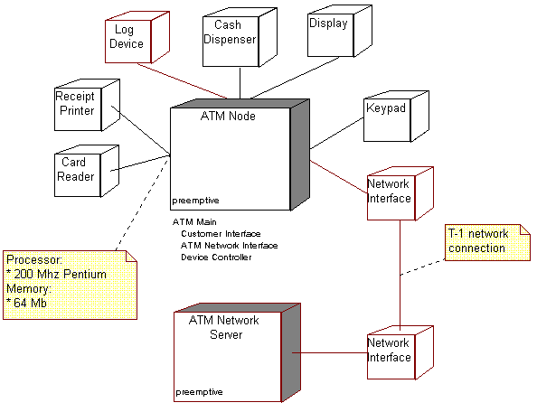
Deployment View for the ATM
The diagram illustrates two Nodes (the ATM itself, which is the focus of this example), and the ATM Network Server, through which all connections to the inter-bank network are made. Though the ATM Network Server is out of scope for the builders of the ATM, we show it here to illustrate how network bandwidth can be documented. The diagram also shows the processes and threads which execute on the ATM Node, which are discussed in the next step Allocate system elements to nodes.
Note the use of annotation to document processor and network capacity. Such documentation can also be presented in the documentation fields of the Node (or the devices), in which case it is not displayed in the diagram.
Allocate System Elements to Nodes
| Purpose | To distribute the workload of the system. |
In this step, system elements are allocated to the nodes defined in the previous step. Deployment can be described from both a logical and a physical perspective.
Logical deployment is where logical elements (classes, subsystems, or instances of these) are mapped to nodes. These may include threads of control. For example, a logical deployment might state that the AuctionManager subsystem is deployed to the Application server.
Physical deployment is where the files are mapped to nodes. For example, a physical deployment might say that the CloseAuctionTimer.class file is deployed to server76.
Distribution is one area where the sum can be, and usually is, less than the sum of the parts. Achieving real benefits to distribution requires work and careful planning. When deciding what elements will be mapped to what nodes, the following needs to be considered:
- node capacity (in terms of memory and processing power)
- communication medium bandwidth (bus, LANs, WANs)
- availability of hardware and communication links, rerouting
- requirements for redundancy and fault-tolerance
- response time requirements
- throughput requirements
- and so on
Elements are allocated to nodes with the intent of minimizing the amount of cross-network traffic; elements that interact to a great degree should be colocated on the same node; whereas elements that interact less frequently can reside on different nodes. The crucial decision, and one that sometimes requires iteration, is where to draw the line. The distribution of processes across two or more nodes requires a closer examination of the patterns of inter-process communication in the system. Often, there is a naive perception that distribution of processing can off-load work from one machine onto a second. In practice, the additional inter-process communication workload can easily negate any gains made from workload distribution if the process and node boundaries are not considered carefully.
Example
The previous example diagram, the Deployment View for the ATM, illustrates for the ATM Node the allocation of processes onto the node. There is a single process (ATM Main), which in turn consists of three separate threads of control (Customer Interface, ATM Network Interface, and Device Controller).