Tool Mentor: Creating a Software Architecture Document Using Rational SoDA
Purpose
This tool mentor describes how to use Rational SoDA to create a Software Architecture Document. SoDA automates the generation of the report so that it is created quickly and accurately. You can generate a Software Architecture Document with either the Microsoft® Word® or Adobe® FrameMaker® version of SoDA. To create this report, SoDA collects architecturally significant aspects from a Rational Rose model. This works only if the model follows the structure and naming convention for the Rose model.
Related Rational Unified Process information: Artifact: Software Architecture Document.
This section provides links to additional information related to this tool mentor.
Overview
This tool mentor is applicable when running Windows 2000, NT 4.0, Windows XP, Solaris, or HP-UX.
To create a the Software Architecture Document using SoDA, use the procedure for your version of the product:
- Use Rational SoDA/Word to generate a Software Architecture Document
- Use Rational SoDA/FrameMaker to generate a Software Architecture Document
Use Rational SoDA/Word to generate a Software Architecture
Document 
- From anywhere in Rational Rose, click Report > SoDA Report.
- When the list of available reports appears in SoDA, select Rational Unified Process Software Architecture Document.
- Click OK to generate the report.
Use Rational SoDA/FrameMaker to generate a Software
Architecture Document
- From the FrameMaker button-bar, click New. Double-click SoDA, then double-click RoseDomain and choose the RUPSoftwareArchitectureDocument.fm template.
- Edit the Connector and enter the name of the model.
- Click File > Save As to save the template to a personal or
project directory.
You may want to change the name of the template to reflect the name of the use case; for example, ConductTransactionsReport.fm. - Click SoDA > Generate Document.
- Review the generated document.
The next time you want to generate this same document, simply open the document and click SoDA > Generate Document.
Structure
and naming convention for the Rose model
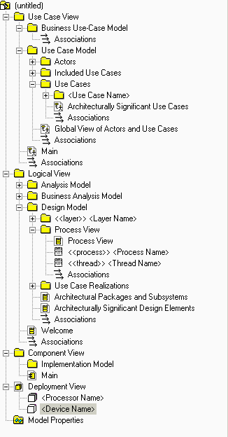 |
The following lists the diagrams
that SoDA extracts from the Rose model for inclusion in the Software Architecture Document:
|